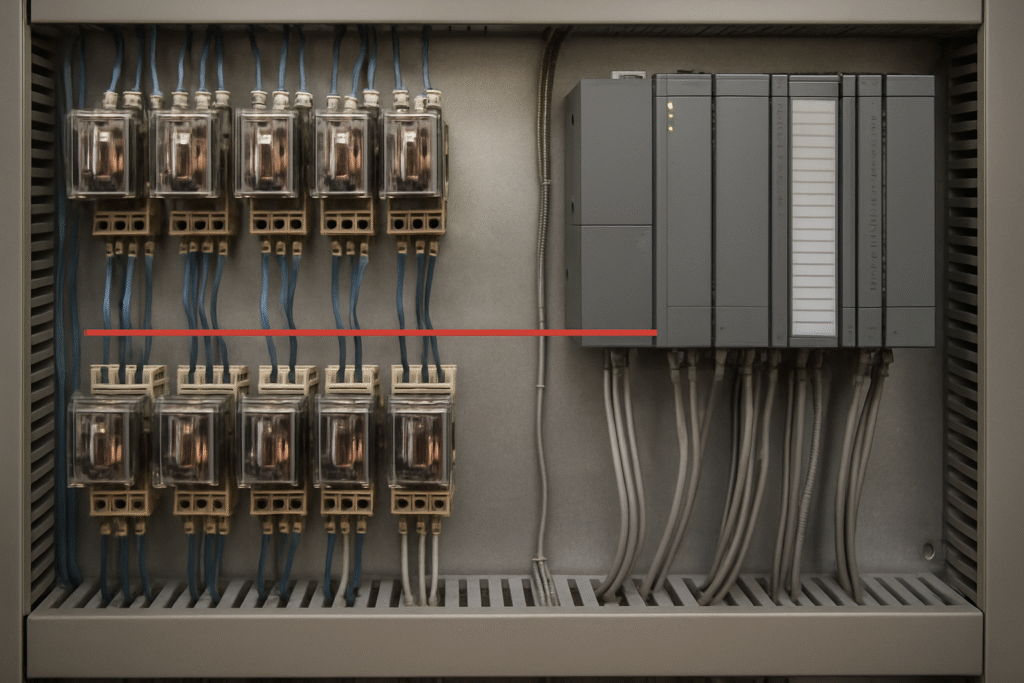
Introduction: The Critical Role of Relay‑to‑PLC/SCADA Integration in Modern Industrial Projects
As industrial facilities advance their automation and protection systems, the interface between protection relays and PLC/SCADA platforms has become a linchpin for operational reliability, safety, and maintainability. Whether in new builds or modernization of legacy plants, the integration of protection devices with automation infrastructure is a frequent source of project risk—manifesting as electrical incompatibilities, isolation lapses, thermal constraints, and unclear interface responsibilities. For plant managers, controls engineers, and capital project leaders, mastering the technical and procedural aspects of this interface is essential for successful project delivery and long-term system performance.
This article provides a rigorous, evidence-based guide to relay-to-PLC/SCADA integration. It draws on recent authoritative sources and industry best practices, and is structured to support decision-makers and engineering leads through technical principles, common pitfalls, standards context, commissioning, and documentation. NavonLogic’s role as a principal-led independent consultancy is clarified throughout, focusing on owner-side review, coordination, and commissioning oversight—not direct relay setting or field wiring. Learn more about our industrial power systems and protection services.
Technical Basis: Why the Protection-to-Automation Interface Demands Rigorous Engineering
The interface between protection relays and PLC/SCADA systems bridges two distinct engineering domains: power system protection (focused on rapid, deterministic response to faults) and automation/control (focused on flexible, programmable logic and data acquisition). The technical demands at this interface arise from:
- Electrical parameter mismatches: Protection relays may operate at higher voltages or currents than PLC I/O can safely handle (FCL Components).
- Isolation requirements: Galvanic separation is often needed to prevent ground loops, cross-system faults, or propagation of transients (Industrial Monitor Direct).
- Thermal and mechanical constraints: High-density panels can lead to overheating, affecting relay and PLC reliability (RY-ELE).
- Functional and safety boundaries: Protection and automation systems may have different design authorities, testing regimes, and documentation standards (EOHM).
Failure to address these technical bases can result in unreliable operation, equipment damage, or safety incidents. A systematic approach—grounded in verified data, standards, and engineering judgment—is required for robust integration.
Common Pitfalls in Protection-to-Automation Interfaces
Industrial projects frequently encounter recurring challenges when integrating protection relays with PLC or SCADA systems. The most prevalent failure modes include:
- Electrical mismatches: Incompatible coil voltages, insufficient contact ratings, or excessive inrush currents can damage PLC outputs or cause unreliable actuation (FCL Components).
- Isolation failures: Absence of galvanic separation can lead to ground loops, nuisance trips, or equipment damage (Industrial Monitor Direct).
- Thermal constraints: Overcrowded panels or inadequate ventilation can cause overheating, contact welding, or premature device failure (RY-ELE).
- Ambiguous responsibilities: Unclear demarcation between protection and automation teams leads to gaps in design, verification, and commissioning.
These risks are amplified in brownfield projects, where legacy equipment, incomplete documentation, and evolving standards increase the likelihood of interface errors. Addressing these pitfalls requires a disciplined approach to design, review, and testing.
Electrical Compatibility: Key Parameters and Decision Table
Ensuring electrical compatibility between relays and PLC/SCADA I/O is foundational for reliable operation. The following parameters must be matched and verified:
- Coil voltage: The relay coil voltage must align with the PLC output specification. Mismatches can result in failed actuation or damage to PLC outputs.
- Contact ratings: Relay contacts must be rated for the voltage, current, and load type (AC/DC, resistive/inductive) of the circuit they control. Underrated contacts may weld or degrade rapidly.
- Inrush current: Some relay coils exhibit significant inrush currents, especially with DC operation. PLC outputs must be rated for both steady-state and inrush conditions.
- Leakage and holding current: For solid-state outputs, verify that leakage current does not cause unintended relay actuation.
Decision Table: Matching Relay Coils to PLC Outputs
| PLC Output Type | Typical Output Rating | Relay Coil Voltage | Max Coil Current | Inrush Current | Recommended Practice |
|---|---|---|---|---|---|
| 24VDC Transistor | 0.5A | 24VDC | <20mA | <50mA | Direct drive possible; verify inrush |
| 24VDC Relay | 2A | 24VDC | <100mA | <200mA | Suitable for most industrial relays |
| 120VAC Relay | 2A | 120VAC | <20mA | <40mA | Use only with AC-rated relay coils |
| Low-power Output | 0.1A | 12VDC/24VDC | <10mA | <20mA | Consider interposing relay for isolation |
Always consult manufacturer datasheets for both PLC and relay devices to confirm ratings and derating factors. For complex or high-reliability applications, interposing relays or optocouplers may be required to ensure compatibility and protect sensitive PLC I/O (FCL Components, RY-ELE).
Isolation Strategies: Galvanic Separation and Interface Protection
Effective isolation is essential to prevent electrical faults from propagating between protection and automation systems. The main strategies include:
- Galvanic isolation: Use of interposing relays or optocouplers to electrically separate protection circuits from PLC/SCADA I/O, especially when circuits operate at different potentials or reference grounds (Industrial Monitor Direct).
- Relay vs. optocoupler selection: Electromechanical relays provide robust isolation and can handle higher voltages/currents, but introduce mechanical wear and slower response. Optocouplers offer fast, wear-free isolation but have lower voltage/current ratings and may be more sensitive to electrical noise.
- Buffering PLC I/O: For critical or high-risk signals, interposing relays buffer PLC outputs/inputs, protecting PLC hardware during faults or field wiring errors.
Isolation requirements are not always prescriptive in standards, but are widely recognized as a recommended practice in industrial automation (EOHM). Engineering judgment—supported by systematic review and commissioning testing—is required to select the appropriate isolation strategy based on system voltage, fault current, and operational criticality.
Mechanical and Thermal Layout: Panel Density, Airflow, and Heat Management
Relay and PLC modules generate heat, and improper panel layout can lead to thermal derating, contact welding, or premature failure. Key considerations include:
- Panel density: Avoid over-concentration of relays or PLC modules in confined spaces. Allow for manufacturer-specified spacing.
- Airflow: Ensure adequate ventilation and, where necessary, forced air cooling. Avoid blocking airflow with wiring ducts or cable bundles.
- Heat stacking: Mount heat-generating devices (relays, power supplies) to minimize thermal stacking and allow heat to dissipate upwards.
Thermal Derating Chart (Illustrative)
| Ambient Temp (°C) | Max Relay Load (A) | Derating Factor |
|---|---|---|
| 25 | 100% | 1.00 |
| 40 | 85% | 0.85 |
| 55 | 65% | 0.65 |
Always use manufacturer data for thermal derating. Thermal management is often overlooked during design reviews and can become a source of reliability problems during commissioning or operation (FCL Components).
Standards and Recommended Practices: Context and Project Review Requirements
Several standards and recommended practices are relevant to protection and automation interfaces, but direct, enforceable requirements for relay-to-PLC/SCADA integration are limited. Key references include:
- IEEE Industry Applications Society active standards: Address motor protection, grounding, and bus protection, but do not prescribe relay-to-PLC interface methods (IEEE IAS).
- IEC 60255 (Protection relays): Defines relay performance and testing, but not automation interface specifics. Edition-specific requirements must be confirmed for each project; the current edition should be verified during project standards review.
- Manufacturer datasheets and integration guides: Provide the most practical, up-to-date information on compatibility, isolation, and thermal management.
Where standards are silent or ambiguous, engineering judgment—supported by systematic review and commissioning testing—is essential. NavonLogic supports owner-side review and coordination, ensuring that relay-to-PLC/SCADA integration aligns with best practices and project requirements. Explore our automation and controls expertise.
Responsibility Matrix: Decision and Interface Assignment Table
| Integration Task | Owner/Project Team | Specialist Partner/OEM | NavonLogic (Review/Oversight) |
|---|---|---|---|
| Define interface philosophy | Approve/own | Advise | Review/coordinate |
| Select relay/PLC models | Specify/approve | Recommend/validate | Review |
| Verify electrical compatibility | Review | Perform calculations | Independent check |
| Design isolation strategy | Approve | Design/implement | Review/flag gaps |
| Panel layout/thermal review | Approve | Design | Review |
| Commissioning test planning | Approve/own | Draft/execute | Witness/review |
| Relay settings/protection logic | Approve | Develop/implement | Not performed |
| Field wiring/installation | Approve | Install | Not performed |
| Commissioning oversight | Own | Execute | Witness/document |
This matrix clarifies the division of responsibilities and helps prevent gaps or overlaps in project execution.
Document and Data Request Checklist for Relay‑to‑PLC/SCADA Integration Review
- Protection relay datasheets (model, coil/contact ratings, isolation requirements)
- PLC/SCADA I/O module datasheets (output/input ratings, isolation, inrush limits)
- Panel layout drawings (showing relay, PLC, power supply, and wiring duct locations)
- Wiring diagrams (schematic and termination details for interface circuits)
- Manufacturer integration guides and application notes
- Thermal management calculations or manufacturer derating charts
- Interface philosophy document (defining boundaries and responsibilities)
- Commissioning test plans and checklists
- Applicable standards list (with edition numbers where available; flag any unverified editions for project review)
- Previous commissioning or maintenance records (for brownfield projects)
Requesting and reviewing these documents early in the project lifecycle supports thorough design verification and commissioning readiness.
Verification and Commissioning Acceptance Steps
Commissioning delays and operational issues often trace back to unverified relay-to-PLC interfaces. A robust verification process during Factory Acceptance Testing (FAT) and Site Acceptance Testing (SAT) is critical. Key steps include:
- Pre-commissioning review: Confirm electrical compatibility, isolation, and panel layout against design and manufacturer requirements.
- Interface simulation: Use test signals to verify relay actuation, PLC input/output response, and correct logic operation.
- Thermal inspection: Monitor panel temperatures under load to confirm thermal management is adequate.
- Fault simulation: Where safe and practical, simulate protection trips and verify correct PLC/SCADA response.
- Documentation and punchlist: Record test results, deviations, and corrective actions for handover.
Refer to systematic guidance from the U.S. Department of Energy and Energy Institute for operational readiness and commissioning process structure.
Sample Commissioning Interface Test Checklist
| Test Step | Expected Result | Pass/Fail |
|---|---|---|
| Apply PLC output to relay coil | Relay actuates, PLC output within rated current | |
| Simulate relay contact closure | PLC input registers correct state | |
| Check isolation (megger test) | No leakage between protection and automation circuits | |
| Monitor panel temperature under load | Within manufacturer-specified limits | |
| Simulate protection trip | SCADA alarm/sequence initiates as designed |
Hypothetical Worked Example: Interface Review in a Brownfield Modernization
Scenario: A manufacturing facility is upgrading its legacy protection relays and PLC-based automation system. The legacy relays have 120VAC contacts, while the new PLC I/O modules are 24VDC. The project team must ensure reliable and safe interface between the two systems.
Steps Taken:
- Document review: The team collects relay and PLC datasheets, wiring diagrams, and panel layouts. They identify that direct connection between 120VAC relay contacts and 24VDC PLC inputs is not permissible.
- Isolation strategy: Interposing relays with 24VDC coils and 120VAC-rated contacts are specified to bridge the voltage difference and provide galvanic isolation.
- Panel layout: The panel is reviewed for adequate spacing and airflow, referencing manufacturer derating charts to ensure thermal limits are not exceeded.
- Commissioning plan: A checklist is developed to verify each relay-PLC interface during FAT and SAT, including electrical compatibility, isolation, and thermal inspection.
- Responsibility assignment: The owner’s team oversees interface philosophy and documentation; the OEM configures relay settings and wiring; NavonLogic provides independent review and commissioning oversight.
Outcome: The systematic approach prevents PLC input failures and ensures reliable operation. All interfaces pass commissioning tests, and documentation is completed for turnover. (Note: This is a hypothetical example; no field results are fabricated.)
Checklist: Key Review Points for Project Managers and Engineering Leads
- Are relay coil voltages and contact ratings compatible with PLC I/O?
- Is galvanic isolation provided where required?
- Are panel layouts thermally and mechanically optimized?
- Have all interfaces been verified during FAT/SAT?
- Are roles and responsibilities for interface design, testing, and commissioning clearly defined?
- Are all deviations from standards or best practices documented and justified?
Use this checklist during design reviews, procurement, and commissioning planning. Learn how NavonLogic supports capital project delivery.
NavonLogic’s Value: Principal‑Led Review, Coordination, and Commissioning Oversight
NavonLogic is a principal-led independent consultancy specializing in owner-side review, coordination, and commissioning oversight for industrial automation and protection projects. Our services include:
- Review of relay-to-PLC/SCADA interface philosophy and design
- Coordination between protection, automation, and commissioning teams
- Verification of interface compliance, isolation, and thermal management
- Commissioning punchlisting, documentation, and turnover review
NavonLogic does not perform direct relay setting, power studies, or field wiring, but provides independent technical oversight to help owners avoid common integration pitfalls and ensure reliable, maintainable automation interfaces. See our full range of services.
Conclusion: Achieving Reliable, Maintainable Automation Interfaces
Effective relay-to-PLC/SCADA integration is foundational to safe, reliable, and maintainable industrial automation. By focusing on technical compatibility, robust isolation, sound panel layout, and systematic commissioning, project leaders can minimize risk, avoid costly delays, and deliver operational readiness. NavonLogic supports owners with principal-led review, coordination, and commissioning oversight—helping bridge the gap between protection and automation in both new and legacy facilities.
For project-specific needs or to discuss your next automation modernization, contact NavonLogic.
Source List
- White Paper: PLC Systems: The Role of Relays (FCL Components, crawled last week)
- Industrial Automation Basics: the Role of Control Relays (RY-ELE, crawled last week)
- PLC Digital I/O Relay Isolation: Why and How to Use Them (Industrial Monitor Direct, February 25, 2026)
- Electrical Control and Protection System (ECPS) Whitepaper (EOHM, published 3 months ago)
- Guidance on meeting expectations of EI Process Safety Management Framework Element 13: Operational readiness and process start‑up (Energy Institute, crawled 2 days ago)
- Commissioning Process for Federal Facilities (U.S. Department of Energy, crawled yesterday)
- Active Standards – IEEE Industry Applications Society (IEEE IAS, crawled 3 days ago)
- As Large Load Interconnection Requests Surge, ESIG Maps the Gaps in a Process the Grid Wasn’t Designed to Handle (ESIG, June 19, 2026)
Publication date: 2026-07-11
Last reviewed: 2026-07-11
Professional disclaimer: This article is for general guidance only and does not replace project-specific engineering, approved studies, OEM instructions, governing codes, or professional judgment. NavonLogic is a principal-led independent consultancy and does not claim licensure, sealing authority, or direct specialist capabilities beyond owner-side review, coordination, and commissioning oversight.